|
|
||
| Home | |
| How-To Listings | |
| General Information | |
| Common Problems | |
| Mondeo Revision History | |
| Contact / Disclaimer Info | |
| Links | |
| SITE MAP / CONTENTS | |
Installing a Trip Computer (Based on Mk1/Mk2 wiring (Mk3 not detailed)) This is a modification you can do to mondeos that don't have a trip computer fitted as standard. Unfortunately all mondeo trip computers are designed for petrol engines and will not work with diesels. The trip computer is a direct replacement (on both Mk1 and Mk2 models) of the clock unit. Fitting the unit itself takes only a couple of minutes but the wiring (if your car isn't pre-wired - All Mk1's and most Mk2's) can take a couple of hours. You need to be aware that to complete the installation of the trip computer on non-wired cars will require you to connect to wires in the engine loom. Disconnecting the battery is recommended for this project. You need:
You may need: (Depending on the wire loom in your car)
Start by removing your old clock. Use the flat blade screwdriver to lever it using the small recess under the clock - also remove the blanking plate to the right of it (Between clock and heated front screen switch). Use the flat blade screwdriver and carefully insert between the small gap between clock and dash - Slowly prise out the clock taking care not to damage the dash panel. Use some masking/insulating tape to ensure you don't scratch it. Unplug the connector on the back of the clock unit and then place the clock to one side. Examine the number of wires going into your connector - if there are more then 5 then you have the dash wiring for the trip computer already in place so all you should need to do is fit the temperature sensor and replace the trip computer to complete. There are however three parts to the wiring loom. From ECU to Connector 1, From connector 1 to the junction box, and from the junction box to the trip. Its the last bit you'll have in place. All UK spec mondeos will have the wiring from ECU to connector 1 so its only the middle bit you need to check you have. Locate the engine connector and the relevent wires (as shown below) as check that they continue through the connector - IE, don't go to one side of it only. Connect the existing wires to your trip computer connector. Mk2 clocks and trips use the same connector so decide if you want to use a pre-wired plug with the extra wiring already complete (cut it off the trip computer loom in a scrapyard) or add the wiring to the existing plug. If you want to change to the pre-wired plug then you need to cut the old clock's plug from your car's loom (cut as close to the plug as possible to maximise cable length) and then crimp or solder to the same colour on the new plug. The wires you should have on the clock connector are:
All change over to the new connector using the same colour wiring with the exception of:
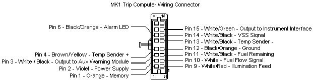
The old Mk1 connector must now be cut off and discarded for the new trip computer connector. There should be a total of 5 wires coming from the old plug and these are shown below:
Cut each wire off in turn and wire them to the appropriate pin of the new connector:
With the existing wiring connected to your new plug connect the trip computer and test it works (remember to reconnect the battery) You should have a fully functional clock, stopwatch and calendar. Turn on the lights and check that the unit illuminates (Mk2 trips are constantly lit with the ignition and don't show a noticeable difference). If all appears to be working correctly then disconnect the battery again and unplug the trip computer to complete the wiring. The trip computer needs to know the following additional information. 1) Amount of fuel left in the tank. 2) Current vehicle speed. 3) Fuel consumption (fuel flow) and 4) External temperature The temperature sensor is an additional unit that sits behind the front bumper to measure external temperature without influence from engine heat. Being as there is no "External" show on the trip computer - it simply shows the temperature) you can decide here if you want to have external or internal temperature indication. If you have, or plan to have, the auxiliary warning module then you should have the temp sender on the outside, in order for the ice and frost warning lights to be effective. If you don't plan on having the aux module then you can mount the temp sender on the inside and have it monitor your cabin temperature instead. You need to take a total of 4 wires out to the engine bay (2 if you are having the temp sender inside) so wrap them together in a small loom. Use two of the 3 meter wires and two of the 5 meter wires for this cable run, the longer two wires need to reach down to the front bumper for the temp sender. This could be classed as the trickiest part of the non-wiring operation as you need to get your mini loom through the bulkhead and sound-deadening material. It's almost impossible to pass it from the cabin to the engine bay so open the bonnet and locate the large rubber grommet in the top right corner of the engine bay. Cut a small slit in the grommet in which to pass your own loom. EXTREME care is required here, if you cut into the existing loom then you'll probably sever the main power feed to the passenger fuse box!!! If you don't fancy cutting the grommet then you can peal it away from the bulkhead and pass your wiring down behind it. Just be aware that if you do this then you risk the chance of water being able to enter the bulkhead/cabin so use some sealer afterwards. Remove the glovebox and you should be able to look up and see if your new wiring loom has come through, if not then you'll need to try again (get someone to help). When its in the cabin make sure it can reach up to the trip computers location with a little excess to compensate for any errors. Working back in the engine bay you need to take the two longer wires down to just behind the front bumper. Although there is a proper mounting position for the temperature sender you can mount it anywhere you choose. I ran mine down the passenger side and mounted it just in front of the horn in the lower left corner of the engine. As long as its far enough away from the engine to not be effected by the heat then you should be ok. If you don't use the proper mounting location then you'll have to use a cable tie to secure the sender. Connect the two wires from the temperature sender to the two wires you have just run down and note the colours. Working back at the trip computer's plug you need to connect them to
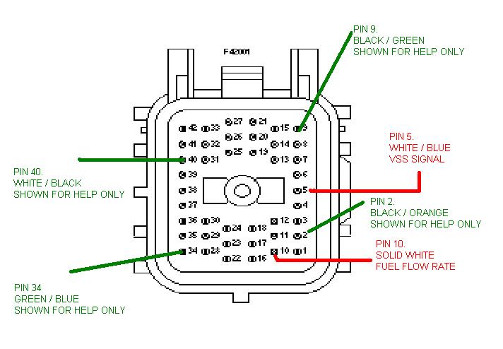
If you have the auxiliary warning module already in place then you'll already have the temperature sender installed but wired to that instead. In this case I would recommend installing a second temperature sender (or splice wires from the existing one) rather then have to disconnect wires and re-route some of the wiring from the auxiliary warning module. When splicing into wires in the engine bay compartment remember that they are subject to weather conditions. You must either crimp or solder the connections and make sure they are 100% insulated. The other two wires go to the large connector just to the left of the passenger side suspension turret. You'll either have 3 small oval connectors here (Early Mk1) or one large square one. In this connector(s) you'll find signals from the VSS (Vehicle Speed Sensor) and from the EEC's fuel flow monitor. It's worth noting that most Mk2 car's have the VSS signal already in the car feeding the speedo and the radio (if speed sence is active). Only Mk1 car's with the auxiliary warning module will have the VSS signal present in the cabin. If you want to find the VSS cable on the back of the radio or behind the instrument cluster (WH/BU) then you can splice it at this point rather then back in the engine bay - you'll still need to connect the fuel flow wire to the engine connector. Now this is the trickiest part of the wiring operation as you have to identify the two wires in this connector out of about 40! Whilst is looks like a nightmare, if you take your time and work over the connector methodically you'll find it's actually pretty easy to ID the correct wire. Just remember that there are some colour repeats so take your time and make sure you count the correct number of wires. We'll start with the Mk2 (Note some late Mk1's also use this connector type) Square type connector and the VSS signal. The pin you are looking for in number 5 and is colour coded WHITE/BLUE. This is the easier one to find as the square connector only has 2 WH/BL wires in it. One running through an outter edge pin (the one we want) and the other coming from the centre of the connector. The second we need is a solid white wire running through pin 10 of this connector. Pin 10 is also on an edge and is at the bottom of the row next to the VSS signal.
The colours shown are what SHOULD be at the relevant pins, however Ford have a habit of changing wiring colours for no apparent reason so don't be alarmed if one or possibly two of the help wires are incorrect. Just ensure that PIN5 is WHITE/ BLUE and PIN10 is SOLID WHITE. SQUARE CONNECTOR NOTE: Cars made from Aug 1998 have a different engine loom fitted, as a result the pin locations are different. Pin 28 (Solid White) is the fuel flow wire and Pin 13 (White/VIOLET) is the VSS Signal. The earlier Mk1 cars will probably have 3 oval connectors in place of the larger square type. You need the top-most connector. Access can be a little tricky if you have the factory intake system as the filter chamber blocks access. The connectors all slide off the pins which aids access a little. On the top connector you'll find the wires you require
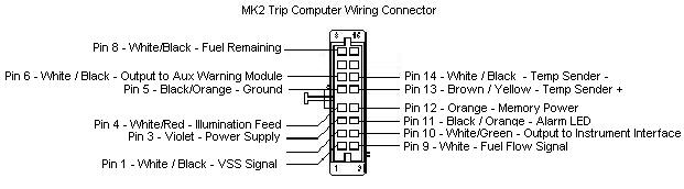
Look at the connector from the engine side and you should be able to see the two wires you need to connect to. Pin 2 (White/Blue) is the VSS signal and is the only White/Blue coloured wire on the connector. Pin 7 (Solid White) is the Fuel Flow signal - make sure you get the correct one as there are two white wires on this connector. Its NOT the one next to the VSS signal wire! Be sure to insulate the joints well and then return to the back of the trip computer to finish the wiring at this end. The VSS signal needs to go into pin 14 (White/Black) of the trip computer module. The Fuel Flow signal connects to pin 10 (White). Working back at the trip computer connector you need to take your VSS Signal into pin 1 (White/Black) and the Fuel Flow signal connects to pin 9 (White) With these wires connected you should have the average speed, odometer, current MPG and average MPG gauges all working. The only one left to connect is for the "Amount of Fuel left in tank". Now I wired a Mk2 trip computer into my Mk1 so I know this works for that and Mk2 cars. Mk1 trip computers may or may not work with this final connection (Anyone who tries it and it works then tell me!)
Under the rear seat base cushion you'll find a circular rubber mat with some wiring coming out of it, prise up the rubber and you'll see the above connector. Take a feed from the the middle pin of the side with 3 pins and run it back to your trip computer. This wire feeds the fuel gauge in the cluster so you could splice it from this point if you don't want to run a long cable up to the trip. Colour variations do occur so don't worry to much what colour the wire is, just make sure its the middle pin. The Amount Of Fuel remaining signal is just a rough estimate on models without the trip as standard, you can use this signal to get a reading on the range function of the trip computer but don't expect it to be all that accurate unless you change the fuel tank sender. Mk1 cars apparently have a very different sender for the trip computer which incorporates another two pins into the fuel pumps sender, therefore if you have to change the fuel pump in the Mk1 for the Mk1 trip version you will need to rewire the entire connection. Back at the trip computer you need to connect this new wire to pin number 11 (White/Black) of the trip computer. Pin 3 (Wh/Bk) is taken to Pin 17 of the auxiliary warning module to provide temperature information. Pin 15 (Wh/Gn) is taken to the instrument interface module (Pin5) to provide a "chime" when you run low on fuel. (50miles remaining) Back at the trip computer you need to connect this new wire to pin number 8 (White/Black) of the trip computer. Pin 6 (Wh/Bk) is taken to Pin 4 of the auxiliary warning module to provide temperature information. Pin 10 (Wh/Gn) is taken to the instrument interface module to provide a "chime" when you run low on fuel. (50miles remaining) Here is the wiring connectors for both Mk1 and Mk2 trip computers so you can work out which wire you need to connect to if you haven't obtained the plugs. Mk1:
Mk2:
|
||||||||||
|
© Copyright Mirez - 22-Aug-2002 - All Rights Reserved. You may link directly to this page from your own however you may not change the content of this page or claim it as your own work.
|
||||||||||